Basements serve many purposes for both commercial and residential buildings, providing additional space for storage, car parking or even perhaps an extra bedroom, all without adding to the height of the building. Our in-depth guide outlines everything you need to know about steel intensive basements.
Contents:
- The Benefits of Sheet Piling
- Sheet Piling Construction Methods
- Designing The Basement
- Design Procedure for Basements
- Design Cantilever and Single-Prop Walls
- Design of Multi-Prop Walls
- Base Stability
- Design of Temporary Supports
- Waterproofing
- Fire Resistance and Fire Protection of Basements
- Pile Driving and Installation

One of the most common methods used when installing a basement is steel sheet piling, a method which helps create minimal disturbance to the surrounding soil and ensures ground stability during the excavation work.
Sheet piles are large sections of sheet materials (usually steel, although others can be used), with interlocking clutches, which are driven into the ground to provide earth retention and excavation support.
These piles offer extremely high resistance, are water tight, and can also be increased in length by welding.
In this post, we’re going to be taking an in-depth look at the use of sheet piling in basement design and construction, taking into account the design considerations, importance of waterproofing and fire resistance, installation methods, and looking at some case studies.
The Benefits of Sheet Piling
First, we’re going to explore the technical, economic and aesthetic benefits which come with using steel sheet piling for the construction of basements.
Speed of Installation
Sheet piles can be easily and rapidly driven into the majority of soil types, which is a huge advantage, especially in fast-track construction projects.
Also since the construction time is less than for reinforced concrete walls, associated site costs will be reduced too.
Durability
Perhaps the biggest advantage of using steel sheet piling in the construction of basements is that it is a high quality product with a strong structural integrity, making it highly resistant to driving stresses from soil, with a very high instant load carrying capacity and an extremely long life once installed, with only light maintenance needed.
Piles will not lose their shape during installation, won’t bulge in soft soil conditions, or be damaged from the installation of subsequent piles, and the close-fitting joints of the interlocking system also mean that the piles create an effective water seal, and an additional expanding sealant can also be brushed into the joints when total water-tightness is required.
Cost Effective
Sheet piling is also usually the most cost-effective solution, as the required pile capacity can be easily calculated before work begins, so you can optimise the piles you use and only pay for what you need.
The high resistance of the piles also means that fewer piles are required per project, with no hidden costs or additional expenses for site clean-up.
In addition, the piles can actually gain capacity as the shaft soil strength increases over time after the installation, and when taken into consideration with the design, this can help to make savings too.
Can be Recycled
Steel sheet piles are a fully sustainable product, as they can easily be extracted from the ground due to their lightweight nature. This means they can then be reused on other projects once the basement has been constructed, minimising waste.
No Disturbance of Existing Ground
Unlike with bored concrete piling, there is no disturbance of the existing ground where the basement is to be constructed, sheet piles are often used in areas where it’s advisable not to drill holes.
And because the wall is installed prior to the soil excavation, the adjacent buildings can be better supported, and potential subsidence can be prevented.
Sheet Piling Construction Methods
Next, we’re going to take a look at the construction methods which are used in the construction of basements and the factors which can affect construction.
Factors Affecting Constructionr
There are a lot of external factors that can impact upon the construction of a basement and how difficult the project will be, including:
- How close by any adjacent buildings are
- Legal rights of nearby residents/businesses
- Conditions of the soil/groundwater
- Proposed depth of basement
- Proposed usage of basement
- Previous usage of the site
- Existing structures and services such as sewage pipes
Principal Basement Construction Methods
Open Excavations
In basements with small and medium retained heights, an open excavation with soil side slopes for stability is the best option, when there is enough space around the building footprint.
There also needs to be enough space for the sides of the excavation to be cut back to form a stable slope.
In these kinds of projects, steps must be taken to ensure that ground water doesn’t flow into the excavation, as this will lead to erosion and slipping of the slopes.
However, bear in mind that in urban sites, where there isn’t much space, it’s often impractical to carry out an open excavation.
Temporary Support
Where there isn’t enough room around the excavation to form a sloping embankment, temporary support is a popular solution.
Steel sheet piling is the most common form of temporary support, and strutting and tie-back anchors are also often used.
Remember that using a temporary wall support is only possible when you can allow some subsidence of the adjacent ground once the wall is removed, and this is unlikely to be the case in many city centre sites.
Permanent Support
When an open or temporary excavation isn’t possible, an embedded wall can be constructed in advance which will then become a permanent part of the structure.
While permanent walls are historically created with concrete, there are benefits to be gained from installing permanent sheet piling instead.
The majority of basements are located in urban and city centre areas, where there is less space available, a mixture of permanent and temporary can prove most efficient.
In these sites, vertical peripheral support is often provided by a cantilever (without propping), but depending on the soil movement during the excavation and the proximity of nearby roads and other services, a cantilever might not be practical.
In these cases, and in deeper basements, more complex methods such as levels of propping will need to be introduced.
To develop these multi-propped, deep basements, in the least time and at the least cost, a couple of construction methods are used, top-down and bottom-up, both of which use steel sheet piling.
Top-Down Construction
In this method of basement construction, permanent works are used early on in the excavation to limit or remove the need for temporary solutions, removing small amounts of soil as you go and providing lateral support, so that ground movement is limited.
Support and retention systems for top-down basement construction include:
- Permanent perimeter steel sheet pile retaining walls
- Horizontal props such as floor slabs or steel frames
- Foundations for basement columns
Top down construction starts with the driving of the sheet piles to the desired depth around the perimeter or the basement, creating a permanent retaining wall.
Next, the columns for the foundations are built, to provide support to the floors. To create the foundations, a hole bored, and filled with concrete up to the formation level of the basement slab as the auger is being removed.
A steel column section is then lowered while the concrete is still wet, to form the foundation, a process which known as the ‘plunge’ column method, and which is repeated until all basement columns are in place.
Once the columns are in place, the floor slabs are constructed. The ground surface will be levelled, and the soil compacted, to create a solid base for the flooring, before concrete blinding and a polythene sheeting are placed, allowing for reinforced concrete slabs to be cast.
Once the soil and temporary base are removed, a smooth concrete surface to the underside of the ground floor slab will be produced.
Using openings in the slabs, the soil can then be excavated, using construction plant with a crane or conveyor belt, depending on the circumstances.
The soil will be removed to the desired level of the first intermediate floor slab, and the process will be repeated.
Finally, the base slab will be constructed either directly on top of the soil below, or as a suspended slab with a void below.
Advantages of Top-Down Construction
- As part of a multi-storey building, top down construction can take place while the building frame is being constructed using bottom up construction from the ground.
- The wall and soil movements can be kept to a minimum, as the basement structure will already be supported laterally before the heavy excavation takes place (this is especially important if the project is next to any significant structures).
- Because there’s a lack of temporary construction, costs are reduced, and you’ll also avoid any potential deformation that temporary works could cause.
- Once the ground floor slab has been constructed, you have a large level suite area to immediately work with.
Disadvantages of Top-Down Construction
- The excavation of soil can provide problems if sufficient access areas in the slabs aren’t provided.
- Ventilation systems will be required for workers during the soil removal stage.
- Planning access holes in the slabs without removing the lateral support of the walls can be difficult.
Bottom-Up Construction
Bottom-up construction involves removing as much as soil as quickly as possible and constructing the basement by conventional methods, with access from above.
Ground and wall movement are limited through temporary measures which are replaced by permanent works later on.
Examples of temporary restraints include steel frames, horizontal tubular struts, inclined or ranking props, ground anchorages and soil berms.
Other Construction Methods
There are also construction methods which use a combination of both top-down and bottom-up.
For example, the site perimeter could be constructed using top-down with the centre being an open excavation for bottom-up construction.
Designing the Basement
Designing a basement requires very careful geotechnical consideration, with a lot of uncertainties when it comes to estimating the earth and water pressure.
We’re now going to take a look at the different types of basement design, the design standards that the project must meet, and the various stages of designing a basement.
Types of Basement Design
When it comes to smaller retained heights (3.5m and below), the issues of soil pressure and bending moments aren’t as important to your choice of sheet pile, and issues such as ease of installation and durability will be more important.
For medium retained heights (4m-6m), the bending moment becomes much more important, and the BS 8002 code of practice for ‘Earth Retaining Structures’ can be used, in conjunction with guidance from a team of both structural and geotechnical engineers to ensure that a safe wall is produced.
Finally, for a deep basement of 6m or more, geotechnical considerations will be key when it comes to the wall type, construction method, propping and design of wall section.
For these projects, a highly skilled and experienced team of engineers will be required to ensure economical and safe construction, and the most sensible option may be a steel intensive deep basement construction.
Building Regulations
The method of basement construction will have an effect on the habitable environment that is achievable in the basement, and what it will be able to be used for, due to potential problems with damp and water ingress.
Firstly, the internal environment of the building must meet the requirements of the Building Regulations 1991.
However, when the construction is below ground water level, there will be additional precautions which need to be taken.
When an external wall or floor is going to be subject to groundwater pressure, refer to BS 8102 ‘Protection of Structures Against Water from the Ground’.
Limit State Design Philosophy
Limit state design philosophy is now the generally accepted standard for European structural design, with old work stress design methods being replace with these methods.
The design philosophy considers two principal limit states:
- Ultimate Limit State (ULS) – Collapse of all or part of the structure
- Serviceability Limit State (SLS) – A state, short of collapse, at which deformation, appearance or condition of the structure becomes unacceptable.
The loading conditions of ULS are usually more severe than at SLS, with ULS considerations more often than not governing design.
Geotechnical design usually follows an essentially working stress philosophy, which in many cases is governed by limits on soil movement rather than on strength.
Designing basements according to limit state philosophy needs to recognise that geotechnical design can be governed by SLS considerations at the same time as the structural design of the walls and props are governed by ULS.
BS 8002 explains this philosophy further.
Design Standards
The Buildings Regulations make references a number of UK and European Standards and Codes of Practice, which we’re going to run through below.
National Standards for Design
BS 8002 – Code of Practice for Earth Retaining Structures
This is an update of the old Civil Engineering Code of Practice No 2 from 1951, which recognises that effective stress analysis is the main basis for assessing earth pressures, and the importance of the effect of movement on the earth pressure on the wall.
Andrew Bond, Chairman of “CEN/TC 250/SC 7 Eurocode 7 – Geotechnical design” says that: “This revision of BS 8002 provides designers with the guidance they need to implement the requirements of Eurocode 7 with regards to gravity, semi-gravity, and embedded retaining walls.
“The standard gives further details on how retaining structures should be designed according to limit state principles and provides information missing from Eurocode 7 but of importance to UK practice. At the same time, advances in retaining wall technology over the past 20 years are reflected in the fully revised text.”
BS 8004 – Code of Practice for Foundations
This standard is used in the design and construction of foundations, whether piled or shallow bearing.
BS 8004 is based on a working stress approach, using lumped factors and safety, using a design approach based on moderately conservative soil parameters, loads and geometry.
CP2
While the CP2 code of practice has been superseded by the BS 8002, it is still used in some temporary design works.
For example, total stress design is applicable to cohesive soils where there hasn’t been enough time for the pore water pressure to dissipate into the soil, a common situation in temporary works such as clays, where undrained soil behaviour and properties are relevant.
BS 5950 – Structural Use of Steelwork in Building
This standard provides a limit state approach to building design, covering the design, construction and fire protection of your steel structures and providing specifications for the materials, workmanship and erection.
BS 8110 – Structural Use of Concrete & BS 8007 – Design of Concrete Structures for Retaining Aqueous Liquids
These two standards are used when designing the concrete floor slabs of the basement, with BS 8007 being used in water retaining structures and BS 8110 in structures where tanking and drainage have been specified.
However, using BS 8007 will lead to a fairly significant increase in the cost of construction because of the additional steel reinforcement that the standard requires.
BS 8102 – Code of Practice for Protection of Structures Against Water from the Ground
BS 8102 provides guidance on those basement structures which are subject to water pressure.
The standard outlines the different grades of internal environments relating to basement usage and performance level and the levels of water resisting construction which are acceptable for each.
Some of the data in this standard is now out of date because of more recent technological advancements in water resistant construction methods, and it doesn’t cover sealed steel sheet piling products, which are very effective as water resistant basement walls.
CIRIA Report 104
This report from 1984 was an unofficial design standard, and while it’s a bit outdated now, it is still used today due to industry familiarity with the report.
The report doesn’t cover multi-prop walls, but its principles of factoring soil strength has been used in analyses of such walls by deformation methods.
Geotechnical Design
The ‘limit state’ is the point at which a structure is on the point of failure, and is no longer in a condition which fulfils the relevant design criteria.
Limit states are general broken down into the following three types:
- Serviceability Limit State
- Ultimate Limit State
- Accidental Limit State
Serviceability Limit State refers to deformations in the soil-structure system that occur under normal working conditions, and could relate to:
- Movement of ground which would cause damage to adjacent buildings
- Movement of ground which would cause off of drainage performance of wall aesthetics
- Leakage through or beneath walls
- Transport of soil grains through or beneath the wall
- Change to the flow of groundwater
- Structural durability
For ultimate limit state requirements, there must be an acceptable margin of safety against the collapse of any elements of the structure under the worst case combination of loading and material properties.
This means that the following factors must have an acceptably low probability of occurring:
- Loss of overall stability
- Failure of a structural element or connection between elements such as a strut
- Failure through ground and structural elements
- Forward rotation or translation of the wall
- Penetration failure
- Toe failure
- Foundation heave failure
- Hydraulic failure
- Passive failure of soil
Finally, accidental limit state refers to ultimate limit states where unintended loading is applied to the structure, such as:
- Surcharge overload
- Damage to temporary works
- Burst water mains
Structural Design
The structural design of the basement to a limit state philosophy can be based either on British Standards, Eurocodes or design guidance documents like CIRIA Report 104 Design of Retaining Walls Embedded in Stiff Clays.
If the geotechnical design has been based on BS 8002 or CIRIA Report 104, it will be most appropriate to perform the structural design to British Standards, including to BS 5950-1 for the steel components of the basement like the sheet pile wall and internal columns and temporary props if necessary and BS 8110 for the design of the reinforced concrete components like the basement floors.
Loading & Design Parameters
The loading for each design case being resisted by the retaining wall will largely consist of:
- Weight of soil
- Earth pressure
- Ground and free water pressure
- Seepage forces
- Surcharge loads
- Superstructure loads such as supporting building frames
- Horizontal and vertical loads on the basement floor
- Temperature
Other geometric parameters to bear in mind:
- Level and slope of the retained ground surface
- Excavation level
- Characteristics of the geological model
Any gross changes in levels should be modelled directly and not assumed to be included in any factors of safety and geometric parameters should represent the most unfavourable values which could occur.
Behaviour and Performance of Retaining Walls
There are a number of uncertainties when modelling retaining wall behaviour during the construction and final configuration phases of your basement project, including:
- Value of soil parameters
- Rate of consolidation in relation to time taken for soil to change from undrained to drained
- Rate of softening on passive side of wall
- Depth of soft and compressive deposits
- Continuity and pressure of water-bearing layers
- Stress state in the ground
- Water levels and drainage boundaries
- Wall stiffness
- Changes in superimposed loading
All of these uncertainties will play into the choice of support system, installation method and excavation sequence that you choose to use for your basement project.
There are no codes or standards to cover these judgements due to the complexity of the interacting factors.
This means that there is a certain level of risk, although this can be mitigated either by over-design, or close monitoring of real wall behaviour.
Predicting Ground Movement
The deeper a basement is built, the greater the risk of subsidence, heave and horizontal soil movement.
This means that there is a need to try and predict soil movements by sound design and careful construction methods.
We’re going to now take a look at the factors which cause soil movement and how you can try to reduce it.
Effect of Construction Methods
The choice of construction method for your basement project, walling technique and period taken for each excavation stage will all influence how much soil movement there will be around the excavation area.
The most common cause of damage to adjacent buildings comes from wall installation methods and problems with lowering the groundwater level.
Most soil movements come prior to the first prop being located, because the walls deflect as cantilevers until the first prop is inserted.
This can be reduced by positioning the top prop as high as possible, decreasing vertical space between the pops and using sheet piles which have a greater stiffness.
Top-down construction is usually used to reduce vertical soil movements by using stiff concrete floors to prop the sheet pile walls, with wall and soil movement minimised with regular propping at each storey.
Some choose to construct the external walls and excavate down to the first basement floor without casting the ground floor. The use of temporary soil berms to support cantilevered external walls in this situation can also help to partly reduce the additional settlement from excavating to first basement level.
Where the soil conditions don’t allow a cut-off against groundwater ingress a top-down method may be beneficial for reducing external soil settlement.
There are a couple of disadvantages to this method though, such as higher excavation costs, risk of an overall delay to the project and space and access constraints.
Soil berms are useful for reducing the lateral movements of sheet piling walls at the periphery of an excavation, as the increase in vertical stress using a small amount of soil is usually enough to reduce lateral movement by as much as 50%.
Replacing the berms with props in short lengths can help to minimise final lateral movement and vertical settlement outside of the excavation.
Data Required for Design
Designing a retaining wall for a basement requires a lot of information and data to be collected, such as the layout and topography of the site, the nature of the ground, water conditions and details of adjacent structures.
Full investigation testing will have to be carried out on the site prior to construction to collect this data, which we’re going to take a look at now.
Ground Water
The ground water levels and seepage pressures will need to be collected, and any potential changes that the proposed basement will cause will have to be taken into account as well.
Soil Properties
Both the stiffness and strength of the soil may need to be tested, in both drained and undrained conditions.
Strength properties include:
- Bulk densities and moisture content
- Shear strength, including the angle of shearing resistance and cohesion intercept
- Soil classification properties such as plasticity index
Stiffness properties include:
- Young’s modulus
- Poisson’s ratio
- Coefficient of horizontal subgrade reaction
- Over-consolidation ratio (OCR)
- Initial coefficient of earth pressure at rest
Remember that the appropriate parameters may change depending on the mechanism or mode of deformation being used.
BS 8002 and CIRIA Report 104 are both useful for helps to determine data for basement design and provide good guidance on soil parameter values.
Determination of Design Soil Properties
Determining design values for soil properties from the data derived from a site investigation can be difficult, and the design values obtained will vary depending on the code of practice, standard or design guidance document being used, so we’re going to quickly describe the differences below.
Design Procedure for Basements
In this section, we’re going to take a look at the procedure for designing a steel intensive basement, before going into more detail on the design aspects in later sections.
Having a good idea of the structure of your design procedure is crucial, so that the designer has a good view of the overall project, not just the immediate stage.
Categorise Basement Type
Firstly, you’ll need to define what the purpose of the basement is going to be, whether it’s for a residential property, office building, or a deep basement such as an underground car park.
The purpose of the basement will dictate how complex the design is going to be, as well as how much advice you will need from a geotechnical engineer.
Site Investigation
A thorough investigation of the site location and the factors such as soil behaviour and water regime is necessary to assess how the basement will need to be designed and constructed.
For example, you may find that the basement is to be built on ‘competent’ ground, with little to no soil structure issues, in which case the geotechnical aspects of the design can be carried out by a normal structural engineer.
However, if you find that the basement will be situated on ‘poor’ ground, where factors such as geological discontinuities and soil behaviour could cause complexities, you may need to consult a more experienced geotechnical engineer.
Identify Internal Environment
To satisfy the requirements of the Building Regulations, you must identify the internal environment of the basement, which allows the designer to decide what measures will be necessary to achieve the required environment.
Identifying this early on is crucial, as changes to the environment later on will have a knock-on effect to the rest of the design process.
Identify Construction Method
There are numerous methods of construction which can be used for a basement, and they have to all be considered thoroughly, especially in urban areas.
The effect that the construction will have on adjacent sites and the potential damage caused by soil movement is the main thing which needs to be considered, and for this reason, permanent retaining walls are often used.
Propping using basement floors is also an effective method, and reduces the need for temporary propping works, which is why top-down construction is often preferred.
Obtain Soil Data
Next, a thorough investigation of the site to obtain soil data is required, and a detailed explanation of the selection and evaluation of soil parameters should be given.
Choose Basement Wall Support Configuration
The wall support for the basement will depend on the depth excavation as well as the soil properties and water regime.
The two most common configurations for wall support are cantilever or single prop and multi-propped walls.
Design for Corrosion
Both uncorroded and corroded section properties need to be known when designing a steel sheet pile wall.
Determine Vertical Load from Building
Any superstructure loads which are acting on the walls of the basement need to be obtained from the building structure analysis.
Unfactored loads for each of the individual components (dead, live load etc.) will need to be obtained as well.
Ensure Wall Stability
Your retaining wall will need to be able to resist vertical loads from the building superstructure, and this applies to both single-prop and multi-prop walls.
The easiest way to satisfy both the vertical capacity and lateral stability is to increase the embedment depth.
Where this isn’t possible, an alternative pile configuration may need to be used.
Confirm Base Stability
Numerous modes of instability have to be tested for and prevented, which are related to potential base heave or hydraulic failures.
Assess Ground Movements
You can assess the ground movements and wall displacements by either accessing a database of information from past construction projects, or by carrying out some more complex analysis such as finite element methods.
Assess the Retaining Wall’s Structural Adequacy
The structural adequacy of the retaining wall must be checked for all loading combinations, including the props too.
Design Bottom Slab
The concrete bottom slab of your basement will need to resist the loads that are acting upon it, but will also need to be water resistant too.
The level of resistance the slab needs will depend on the proposed usage and internal environment of the basement.
Design Cantilever and Single-Prop Walls
In this section, we will be exploring the methods which can be used to design cantilever and single-prop walls.
Your cantilever and single-prop walls will need to be able to prevent the limit states being exceeded, which will be achieved by:
- Deciding on an adequate depth of embedment, to limit the movement of soil and satisfy the stability requirement
- Satisfying the requirements for vertical load resistance
- Choosing wall section size to resist all external loads which will act upon it
The first thing to do will be to determine the loads which will act on the wall, such as soil and water pressures, vertical loads and surcharges.
Once you know these loads, you can calculate the depth of embedment of the wall and check whether the wall will be able to resist the vertical loads.
Finally, once the length of the wall has been decided upon, you can calculate the internal forces which will act on it, such as bending moments and shear forces.
Wall Stability and Embedment Depth
The most common reason for failure of retaining walls is of overturning, so checks should be made, especially in waterfront structures, or ones on sloping ground, that a deep-seated slip plane doesn’t form behind and below the wall.
The minimum depth of embedment for the wall can be calculated from the equation defining moment equilibrium: restoring moments should exceed overturning moments by a margin defined by the relevant codes of practice or standards.
For propped walls, it’s assumed that there is enough embedment to prevent any horizontal movement, but rotation can still take place at the toe, with the wall rotating as a rigid body, around the prop.
The required embedment depth will be determined by equating moments about the prop, assuming fully mobilised active and passive earth pressures.
Considering the horizontal equilibrium will allow the necessary prop force to be calculated.
Design Methods
To ensure that restoring moments exceed overturning moment by the required safety margin, there are two methods.
These are, a limit state design method (factor on strength method) or a single (lumped) factor of safety, which applies to the bending moment (factor on moment method).
Factor on Strength
With this method, the soil strength parameters used to derive the earth pressure coefficients are reduced by dividing by appropriate factors.
These can either be partial factors for an ultimate limit state or factors which represent the soil strength to be considered for a serviceability limit state.
This method is a reliable and consistent one, which factors the parameters with the greatest uncertainties, making it the preferred method of both CIRIA Report 104 and BS 8002.
However, be sure to exercise caution, as the calculation of embedment depth depends on the chosen safety factor.
Factor on Moment Methods
With these methods, earth pressure distribution is worked out using the fully mobilised design soil strengths and the geometry determined such that restoring moments exceed overturning moments by a designated margin.
This margin is calculated to a predefined lumped factor and there are three main methods to determine the embedment depth, and they are:
- Burland-Potts Method
- Gross Pressure Method
- Net Total Pressure Method
Comparison of Methods
Comparisons of the methods outlined above have shown that there is no unique relationship between the results gained by the different definitions of the lumped factor, and that the choice of method is largely one of which works easiest for you.
Since the publication of BS 8002 the ‘Factor on Strength’ method has become most popular for stability considerations.
The designer should consider all of the design methods available and be sure to keep up with all of the latest developments and new codes of practice.
Vertical Load Resistance
Where a retaining wall resists vertical loads from a building superstructure, a method of predicting the axial capacity of sheet piles will be needed.
Because BS 8004 gives minimal information on the use of sheet steel piles, it’s recommended to use the SCI Steel Bearing Piles Guide for design.
Ultimate Axial Capacity and Load Transfer
Sheet piles subjected to loads parallel to their longitudinal axis will support the load party by shear generated over their length, due to soil-pile wall friction and partly by normal stresses which are generated at the base or tip of the pile, due to the end bearing resistance of the soil.
To design a retaining wall which will resist the axial load acting on the top of the wall, the overall behaviour of the wall must be considered.
With an unpropped wall, as the wall deflects under the lateral load, the soil on the active or retained side moves down relative to the wall, while on the passive side, the displaced soil will have to move upwards.
If the wall displaces in a downward direction under an axial load at the pile head, the shaft friction on the active side will diminish.
It can usually be assumed that wall friction resistance is mobilised only when soil is displaced upwards, along the wall bounded between excavation level and the pile tip.
This means that only the side of the all which is in contact with the passive soil zone is considered when determining the contact area.
Where the depth of embedment needed to achieve stability against overturning isn’t enough to provide the necessary vertical resistance capacity, the depth should be increased as needed to carry the vertical load.
It can be assumed that any extra length of pile will have friction acting on both faces of the pile.
Determination of Wall Friction Surface Area
Sheet Piles and High Modulus Piles
The surface area of sheet piles can be obtained from the manufacturer’s literature, and can generally be taken as the ‘coated area’.
Because wall friction is assumed to only act on the passive zone of the soil, the area in which shaft friction acts is half of this value.
This area per unit length is multiplied by the embedment depth of the pile below excavation level, over which shaft friction is mobilised.
Closed Section and H Piles
The effective surface area for shaft friction resistance of box, tubular and/or H piles can be affected by whether a ‘soil plug’ is formed at the tip of the closed section.
If no plug is formed, the surface area is given by the summation of the inside and outside shaft surface areas.
If a plug is formed, then the surface area is only based on the outside surface, because only skin friction on the inner surface is take up in supporting the end bearing resistance.
If it isn’t certain whether a plug will or will not form, then the designer should consider both eventualities, and adopt the one with the least resistance.
For closed sections, the surface area of an H pile section will depend on whether a plug is formed at the tip.
If no plug is formed, the surface area is given by the total surface area of the H section. If one is formed, the pile is assumed to be a rectangular section with external dimensions of the H pile, however, it’s worth bearing in mind that plug formation is very rare in most UK applications for basements.
Determination of Base Resistance Area
Sheet Piles
The effective area at the tip of sheet piling producing base resistance usually assumes that there is no soil plugging present. If this is the case, the area is given by the cross-sectional area of steel.
Closed Section and H Section Sheet Piles
For closed and H section piles, the area to be used when calculating base resistance is the full cross-sectional area of the pile base comprising the pile wall, as well as any soil plug,
The ultimate pile base resistance across the whole cross-section is compared with the internal soil plug skin friction as well as the pile wall tip end bearing, with the lesser being taken.
Design for Lateral Loading
Understanding the structural forces which act on retaining wall means determining the bending moments, shear forces and axial forces.
The loads which cause the forces occur due to water and earth pressures, surcharges on the surface of the soil and potentially loads from the building superstructure.
Structural forces acting on the retaining wall due to lateral forces are worked out using one of two methods.
The first is to model the soil-structure interaction effects using advanced analytical methods, whereas the second is to use a simplistic distribution of earth pressures assumed in the limit equilibrium method.
Soil-Structure Interaction Method
The pressure distributions which occur in the design configuration of the wall can be modelled using the soil-structure interaction method.
Structural forces and displacement are determined for the particular design situation being considered, and the stiffness of the retaining wall and soil, method of construction and initial stresses in the soil are all taken into consideration.
This method may be appropriate when:
- Distribution and magnitude of soil movements need to be estimated
- Effects of construction stages on wall behaviour need to be studied
- Influence of high initial in-situ at-rest soil stresses need to be analysed
- Wall and/or soil flexibility effects need to be modelled
Limit Equilibrium Method
Bending moments and shear forces in the wall and forces in the prop due to the pressures assumed in the limit equilibrium method can be calculated either using computer software or manually.
Where a limit equilibrium method is to be used to determine structure forces, CIRIA Report 104 should be referenced, and it provides two methods to calculate structural forces acting on cantilever and proper retaining walls.
These are termed the Ultimate Conditions method and the Working Conditions method, with the report recommending that the Ultimate Conditions method should be used.
Design of Multi-Prop Walls
Multi-prop walls are highly redundant structures, and the degree of soil structure interaction can have a big impact on the distribution of forces and moments.
The construction method will also have an effect on the earth pressures which act on the wall.
While numerical methods are considered to be the best for analysis of this type of structure, simple, empirical methods can also be useful for obtaining approximate solutions.
For a more accurate analysis of a multi-prop wall, deformation methods should be used, as they consider soil-structure interaction and calculate the forces acting on the wall and supports and calculate wall deflections.
Simple Methods
The more simplistic of limiting pressure methods don’t satisfy all of the requirements to simulate soil-structure behaviour, particularly the compatibility or displacement boundary conditions, which means that these methods can only ever be approximate.
While earth pressures on multi-propped walls are hard to predict, simple methods based on classical earth pressure distributions are often used.
To perform a simple analysis, some large assumptions need to be made. Using the assumption that active conditions act on the back of the wall and passive conditions act on the front, Liao and Neff (1991) introduced the mobilised earth pressure coefficients to improve the earth pressure distributions and make them more realistic.
Once the earth pressures acting on the wall are estimated, it’s possible to calculate the wall bending moments and support forces, but a number of further assumptions still need to be made, which has led to two main methods, the hinge method and the continuous method.
Hinge Method
The hinge method allows for the structure to be analysed at successive stages of the construction, modelling the retaining wall as additional supports are added.
The hinges (positions of zero bending movement) are assumed to occur at all prop levels except the first.
The spans between the props are designed as simply supported beams which are loaded with the earth and water pressures.
The span between the lowest prop and the excavation level is designed as a single-propped embedded wall with its appropriate earth and water pressures.
The analysis is then undertaken using a stage by stage basis, carrying out excavation to the sufficient depth to allow the next level of support to be introduced.
It’s possible that the support loads and bending moments which are calculated for a stage of excavation are exceeded by those from a previous stage, so the highest values of calculated force and bending moments need to be used for design purposes.
This method allows you to calculate the depth of penetration needed to give a factor of safety against rotational failure, because the lowest span in treated as a singly propped wall, so it can be analysed as such.
While this is great for showing that a given factor of safety has been achieved, it should only be considered an indicative value, because the rest of the piled wall hasn’t been taken into consideration and failure will not be in the form assumed.
This method is explained in detail in BS 8002 and the British Steel Piling Handbook.
Continuous Beam Method
This method assumes that the wall acts as a continuous beam, supported at the prop positions and by an additional fictitious support at the point below excavation level, where the net total earth pressure on the back of the wall is below zero.
Only positive net total pressures are taken into account in this analysis, with the wall below the fictitious prop being ignored.
A numerical procedure in which the beam is represented by finite difference or elements is usually taken in order to obtain a solution, and it is possible to treat the props as either rigid, or with a prescribed stiffness.
This method yields the distribution of shear force and bending moment in the wall and the prop loads.
The analysis is carried out in stages of the construction sequence, such as:
- Excavate to a depth allow the erection of the first level of props (i.e. Cantilever wall)
- Keep excavating to allow second level of props (i.e. Single-prop wall)
- Further excavation allows erection of third level of props (i.e. Multi-prop wall)
This process continues on, including backfilling and alterations, and it’s important to remember that the prop loads and bending moments during the earlier stages may be greater than at later stages, and should be used for the design of the structural members.
This method is described in more detail by Tamaro and Gould (1992).
Deformation Methods
Deformation methods, using a soil-structure interaction approach provide much more realistic representation of a retaining wall’s behaviour, by taking the wall and soil stiffness, in-situ soil stresses and load distribution capability of the soil and wall continuum into account.
These methods predict the earth pressure distribution which acts on the design configuration of the wall.
As the stiffness of the wall and soil are modelled, the earth pressure profiles which are predicted compare well with actual earth pressures.
There are also many other more complex methods where the soil is modelled by factors such as boundary element, finite difference and finite element numerical approximations.
The method chosen should be the one which offers a level of simplicity consistent with adequate results.
Beam on Elastic Foundation Methods
The simplest soil-structure interaction method is the Winkler spring model (beam on elastic foundation, where the soil is modelled as a spring.
Power series, finite differences, distribution and discrete element methods are often employed for the solution of the governing differential equations.
The elastic foundation is assumed to generate reactive pressure proportional to the deflection, which is known as Winkler’s hypothesis.
The response of the soil is often characterised by a spring constant, which is related to the coefficient of subgrade reaction.
The coefficients or horizontal subgrade reaction which are recommended by Terzaghi are usually used.
The subgrade reaction approach is usually used for soil-structure interaction due to how easily it can be applied.
The soil mass is usually modelled as a series of isolated horizontal springs, or with some form of interconnection.
The initial values on each side of the wall are allowed to reach equilibrium in a series of iterations with numerical methods such as finite elements or differences, until earth pressures lie between at rest values and active values on the retained side, and between at rest and passive on the excavated side.
The effectiveness of temporary soil berms is rarely model accurately in these programs. When soil stiffness is input in terms of subgrade reaction values, there is sometimes a lack of confidence from the user in the selection of accurate values.
Programs which are based on elastic interaction factors sometimes have difficulty applying the wall friction or adhesion accurately.
Stressed and unstressed props are simulated by additional springs of required stiffness at the appropriate level.
Most of the time, the bending moments and shear forces internal to the wall are insensitive to the values of the chosen stiffness used in the analysis.
However, computer support forces in a prop have a greater magnitude than ones obtained from empirical, more simplistic methods.
In addition, predicting wall deformations using the deformation method can only really be taken as a rough estimate.
When possible, be sure to carry out checks to compare field measurements with those obtained from your analyses.
Commercially available numerical analysis software product are also commonly used by design practices such as WALLAP and FREW.
Computer Methods Based on Continuum Models
Computer methods based on continuum models include finite element, boundary element and finite difference numerical approximations.
The main advantages of using these types of methods is that they allow you to model wall and soil deformation and stress in a sequence of operations which follows your actual construction stages.
These analyses show both the immediate deformation and other time-dependent changes related to pore pressure equalization.
There’s no need for pre-judged failure modes as these are all revealed as part of the analysis, but low strain values of soil stiffness are essential in these approaches.
Finite Element (FE) Methods
Geotechnical FE packages offer many different models which range from a simple elastic models to highly sophisticated elasto-plastic strain-hardening and softening models.
Choice of model will likely come down to the selection of appropriate soil parameters, as well as how much of the complexity has to be modelled to ensure a realistic result.
Some of the widely used packages in the UK include CRISP-90 and the Imperial College Finite Element Package (ICFEP).
Finite Difference Analysis
Finite differences methods (FDM) model materials in zones, defined by a gridwork, with each zone prescribing stress-strain behaviour (such as elastic or plastic).
This method uses basic equations of motion and a time-stepping process to calculate the accelerations, velocities and displacements of zone mass.
The strains obtained are then used in a constitutive law to determine the corresponding stresses.
Boundary Element Analysis
The boundary element method (BEM) is a numerical method for solving boundary value problems governed by different equations.
The BEM usually links boundary stresses to boundary displacements, with only the boundary of the domain needing to be discretized, not the interior.
The BEM method gives a smaller system of equations and noticeable time savings, and is particularly suited to three-dimensional foundation problems.
Base Stability
There are a couple of modes of instability which can occur in supported excavations, which include:
- Base heave
- Hydraulic failures
Base Heave
One form of base heave can arise when there is excess pore water pressure in underlying soil layers.
If a thin layer of clay overlying sand or grand with a high enough pore water pressure is present, then the clay can be forced into the base of the excavation.
A simple calculation can be used to compare the weight of the clay layer to the pore water pressure, which will indicate the potential for failure.
Base heave can also occur when the soil at the base isn’t strong enough to support stress being imposed by the adjacent soil.
Again, this will cause the base to fail, with soil being forced upwards into the excavation, with large movements in the adjacent ground.
This type of failure can potentially occur during construction or before any base slabs are installed, an analysis is usually carried out using the undrained shear strength.
There are two methods to calculate the critical depth, one by Terzaghi, and one by Bjerrum and Eide, with other methods building upon these.
The Bjerrum and Eide method is the preferred, because it has been found that the Terzaghi method only works if the width of the excavation is large enough compared to depth, and the clay is comparatively homogeneous without a stiff upper layer.
The Bjerrum and Eide Method
This method considered the bottom heave to be the reverse of the standard foundation failure problem, and that the shear stresses mobilised in the soil are caused by the material being removed from the excavation.
Means of Ensuring Base Stability
If the proposed design of the excavation leads to unacceptably low safety factors regarding base stability, there are measures you can take to extend the depth, such as:
- Extend the retaining wall to a competent stratum, so that the wall stops the retained soil from being displaced into the excavation. (This method will lead to higher prop loads)
- Dig a series of smaller excavations with a reduced plan area. This will change the foundation’s aspect ratio, giving an increased bearing capacity factor and factor of safety.
- Excavate under water or bentonite mud, reducing the unloading of the excavation. Bear in mind that this method requires flooding the excavation, and is therefore often undesirable.
- Increase soil strength before excavation, either by freezing, grouting or in-situ mixing.
- Reduce the excavation depth by removing soil adjacent to the main excavation.
Design of Base Slab and Foundations
The choice of foundation in clay soils needs to be able to allow the possibility of water pressure build-ups in future, as well as potential heave of play due to reduced vertical effective stress below excavation level, all while providing enough support for the internal structure.
A piled foundation will be required for a top-down construction, which can be achieved through the use of the bored pile and plunge column foundation system.
Bottom-up constructions will require pad foundations to support the internal columns of the basement.
Water pressure build-up under the base slab which is caused by bottom-up construction could require tension piles or vertical ground anchors to prevent long-term flotation of the structure.
Alternatively, you could provide drainage under the base slab by using land drains laid to falls and bedded in pea gravel.
The drain feeds a sump, fitted with pumps, which lift the water up to a local surface drainage system.
To prevent large heave forces acting on the underside of the slab, polystyrene slabs can be used as compressible filler material to form a void.
However, if a drained void is used, the magnitude of long term settlements around the excavation could be increased.
This could prove to be a problem in basements which are being built next to sensitive structures.
Alternatively, you could construct a stiff, heavily reinforced, base slab and a retaining wall with a deep toe, to provide long-term support for the external soil.
If pad foundations are being used to support the internal columns, they can also be used to give support to the suspended base slabs.
In such cases, the effects of long and short-term heave movements on the relative movement of the pads and slab will need to be assessed.
Hydraulic Instability in Granular Soils
If there is groundwater above the base of the excavation, and if the toe of the wall doesn’t penetrate into an impermeable layer, flow will occur under the wall and up into the base of the excavation.
This will lead to a loosening of the bottom soils, and in turn, a collapse of the wall or loss of bearing capacity.
The best way to prevent this is dewatering, although in deeper excavations, penetrating the wall to a depth to interpret the potential flow lines with high heads of water may prove to be more economical.
Remember that during construction, before the slab has been cast, the corners of the basement are at the greatest risk from piping.
The penetration depth needed to stop piping occurring is a function of the pressure head between the water table and excavation bottom, the ratio of excavation width to net head, and soil conditions below excavation bottom.
Typically, a wall penetration giving a safety factor of 1.5 to 2.0 against piping is usually considered to be appropriate to prevent this failure.
In situations where it isn’t feasible to obtain a suitable depth of sheet pile penetration, or where such a depth is uneconomical, other measures can be used, such as:
- Well points from the original surface level, reducing the water level in the excavation. Can be used for homogeneous soil conditions or when permeability decreases with depth.
- Pressure relief wells at the base of the excavation, suitable in situations with a thin impermeable layer of soil overlying permeable soil close to the base of the excavation.
- A filter later in the base of the excavation, which provides weight and prevents upward movement of soil particles with the inflowing water.
Design of Temporary Supports
In this section, we will be looking at the design of temporary supports such as props and soil berms.
Temporary props are useful in situations where bottom-up construction is being used, although less so in top-down constructions, where support is provided by the very stiff concrete floors, although props can be used as well.
Steel sections such as tubulars, box sections and universal columns are most commonly used as temporary props, with soil berms being used either on their own or with temporary props.
Single-Prop Walls
In the case of single-prop walls, limit equilibrium methods are usually sufficient to determine support force reliably.
Multi-Prop Walls
There are a number of empirical methods used to determine forces on temporary props, the most common of which being the ‘pressure envelope’ method, developed by Terzaghi and Peck, which is included in BS 8002.
A second method, the ‘distributed prop load’ method is presented in CIRIA Report C517, and we’ll discuss both here.
Pressure Envelope Method
The envelope method provides an empirical way of estimating the maximum prop loads for a multi-prop wall.
The envelopes are taken from measurements of strut loads in real excavations, with field observations consisting of measurements of loads carried by the props at one or more vertical cross-sections of the excavations.
The magnitude and distribution of earth pressure muse be inferred from the prop loads, because reliable measurements must be inferred from prop loads, and it’s important to know that Peck’s pressure diagrams don’t represent the actual earth pressure, or its distribution with depth, but load envelopes from which prop loads can be evaluated.
Pressure which is calculated like this is known as the apparent earth pressure, and if this is known, the corresponding prop loads can be worked out by following the reverse procedure.
Each prop should be designed for the maximum load which it may be subjected to, and the design of the prop should be based on the envelope of all apparent pressure diagrams taken from the measured prop loads.
The conditions for the Peck method to be applied as are follows:
- Excavation depth of more than 6m
- Sand is assumed to be drained
- Clay assumed to be undrained
- Bottom stability must be checked separately
- Envelopes for clay are only applicable for short term conditions, and might not give realistic estimates of prop loads in the long term
Difficulties which are associated with this method include:
- Classifying clays and sands
- Treating groundwater
- Selecting the right value of undrained shear strength for a soil profile with varying undrained shear strength
- Treating soil profiles with layers of sand and clay to treat silt
All of these issues will require judgement on an individual basis by the designer.
The pressure envelope method isn’t used to determine forces acting on the sheet pile, and bending moments and shear forces are better obtained through simplistic methods based on classical pressure distribution or deformation methods.
Distributed Prop Load Method
This method was developed in 1999, published in CIRIA Report C517, based on the pressure envelope method.
This method improves upon Peck’s method, giving the load magnitudes as characteristic values rather than maximum values, which can be used in limit state design as appropriate partial factors can be applied for the ultimate and serviceability limit states.
The data presented is classified as either class A, B, C or D, based on the type of ground retained by the excavation.
Class A: Normally and slightly overconsolidated clay solid (soft and firm clays)
Class B: Heavily overconsolidated clay soils (stiff and very stiff clays)
Class C: Granular/cohensionless soils
Class D: Mixed soils (walls retaining both cohesive and cohensionless soils)
There are further subdivisions for classes A and B, splitting them into flexible and stiff walls, and class AF walls (flexible walls retaining soft clay soil) have been divided even further based on their base stability into ‘stable’ and ‘enhanced stability’. In addition, class C walls can be divided into ‘dry’ and ‘submerged’.
The engineer should check that the wall embedment is deep enough to satisfy the assumption that the soil in front of the toe of the wall supports the wall between the base of excavation and halfway toward the lowest prop.
This is likely to be satisfied unless the wall has a lower factor of safety on overall lateral stability.
Temperature Effect on Props
Increases or decreases in temperature props from their installation temperature will cause them to either expand or contract.
If the props are restricted, or aren’t allowed to expand freely, an additional load will be generated in the prop.
If the degree of restraint will allow only some expansion, lesser prop loads will result, and flexible sheet piles will allow a degree of restraint of anywhere between 10-40%.
The Peck envelope method is based on maximum measured loads and includes some temperature effects, and deformation methods will not usually include temperature effects, although they are usually added to the predicted loads after analysis.
Currently, there’s no common approach for the design of props loaded as a result of temperature increases above installation temperature, although it’s recommended to follow guidance found in BS 5400-2.
Typically, a small temperature range of say 10˚C is chosen, with the assumption the prop is to be completely restrained, and if a larger range such as 30˚C is adopted, it’s assumed that the perhaps only 50% of the fully restrained value is attained.
Temporary Support of Retaining Walls Using Soil Berms
CIRIA Report 104 outlines the current methods used for assessing the performance of soil berms for temporary support of retaining walls, with these methods being based on either empirical solutions or numerical analyses.
The two most popular methods, put forward by Fleming et al, are:
- Considering the berm as an increase in the effective ground level on the passive side of the wall. Design height of the berm is restricted to a third of the berm width, and the increase in effective ground level is taken as half of the berm design height.
- Converting the weight of the berm to an effective surcharge acting at the final excavation level on the potential passive failure zone.
These methods are fairly over-conservative, because they don’t take the lateral resistance provided by the soil berm into account and no information on the performance of the soil berms at the serviceability limit state where working loads act is given either.
Methods involving numerical calculations include:
- The use of a slope stability solution, where forces from the wall and weight of the berm are included.
- The use of a Coulomb wedge analysis for a selection of potential failure surfaces, starting at the toe of the wall. The passive force acting on the front of the wall is assumed to comprise a triangular stress distribution acting between the top of the berm and toe of the wall.
All of the methods have drawbacks, and lots of research has been undertaken to try and improve them.
Three dimensional finite element analyses with factor of safety calculations have been carried out to develop less empirically based methods, which has led to design aids using charts being developed to rationalise the design of berms and produce economy in their use, enabling suitable sized berms to be chosen.
For more information on the design of soil berms, refer to TRL Report 398: ‘Design Guidance on Soil Berms as Temporary Support for Embedded Retaining Walls’.
Waterproofing
Waterproofing is crucial in the construction of basements, no matter how dry the surrounding soil may be.
As well as the ground moisture which will be present, rainwater will also soak into the ground from drains and surface flooding, and without taking steps to prevent it, water will soon start to seep through the joints and cracks of the basement through flow under pressure and capillary action.
Water vapour transfer could also occur from ventilated cavities in lined walls, and intrinsically permeable materials such as concrete and masonry will leak water into the basement throughout its life.
However, a steel sheet piled wall is intrinsically impermeable, so won’t have any seepage problems, so long as the clutches are sealed.
This said, the guidance on waterproofing basements largely relates to concrete wall construction, as opposed to permanent steel sheet piles.
Here we’re going to take a look at:
- The requirements of the internal environment
- The evaluation of external ground conditions
- Protection against groundwater seepage
- Water and vapour resistance to individual elements that comprise the structure to achieve required resistance
This should all be taken alongside the existing guidance available in the BS 8102 code of practice: “Code of Practice for the protection of Structures Against Water from the Ground” from 1990.
Internal Environment
BS 8102 should be referred to for guidance on any parts of the basement which will be subject to groundwater pressure, and it refers to four different ‘grades’ which are defined as such in CIRIA 140.
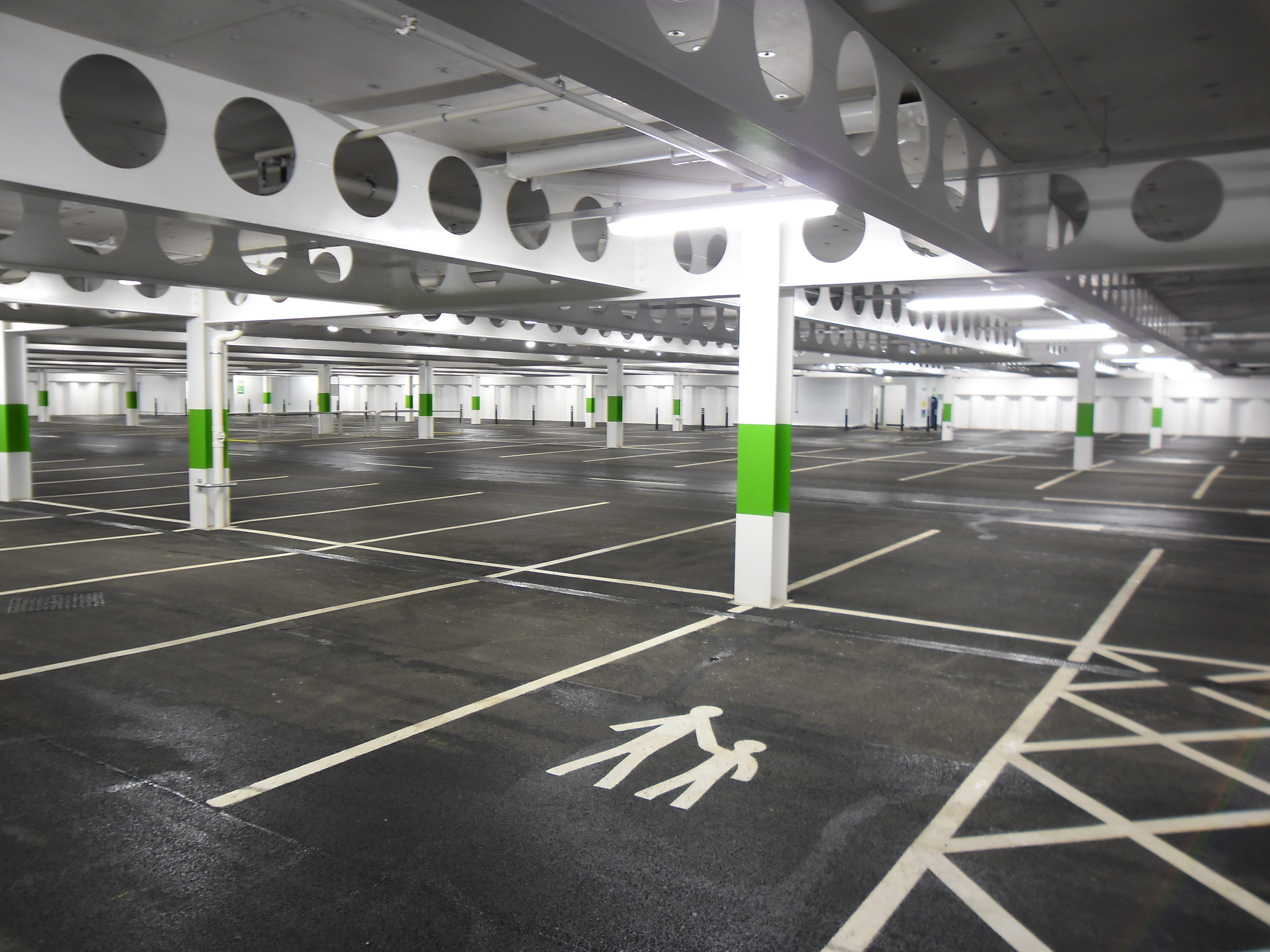
Grade 1 – Basic Utility
Basements used for car parking, plant rooms (excluding electrical equipment) and workshops. Allows for some seepage and damp patches to be tolerated.
Grade 2 – Better Utility
Used for workshops, plant rooms (requiring drier environment) and retail storage areas. Allows no water penetration, but high humidity.
Grade 3 – Habitable
Used for ventilated residential and working areas such as offices, restaurants and leisure centres. Dry environments.
Grade 4 – Special
Used for archives and stores which require a controlled humidity. Carefully controlled dry environments.
Forms of Water Resistant Construction
BS 8201 contains recommendations for minimising and preventing the entry of water, although it was written with concrete and masonry in mind.
Use of sheet piling is not covered in this document, but it is considered to be a structurally integral protection system.
A combination of protection types is often proposed, such as clutch sealants, which are described below.
Prevention of Water Seepage Through Sheet Pile Walls
Steel sheet piles are comprised of a number of interlocked pile sections, and water seepage can only occur at the interlock points, as the steel plate is completely impenetrable to water.
But if any gaps in the interlocks are properly filled, then sheet piling can be make completely waterproof.
Various vertical and horizontal sealing systems have been applied to sheet piling walls to make this possible, with vertical systems applying to the interlocks of the piles, and horizontal ones stopping water ingress at the junction between the pile wall and base slab.
We’re going to take a look at the construction of water resistant sheet piling walls and the techniques which can be used, as well as the performance that can be expected from them.
Vertical Sealant Systems
There are a number of sheet pile clutch interlock systems available, such as:
- Non-swelling sealants
- Hydrophilic sealants
- Combination systems
- Welded interlocks
Whether these systems can be used depends on a number of factors such as:
- Driving conditions (nature of soils and installation method)
- Water pressure requirements
- Permeability requirements
- Durability requirements
Note that for those systems which rely upon a pre-applied sealant, the joint integrity is dependent on the driving conditions and installation techniques, and advice should be sought from the piling manufacturer or contractor.
Non-swelling sealants
These include hot casting bituminous and compounds based on vegetable oil as well as flexible resins based on epoxy.
Hot casting compounds will become viscous once they are heated, giving them a treacle –like consistency, which is poured into the piling interlocks.
Flexible epoxy resins on the other hand have a rubber-like consistency which is pumped into the interlocks.
Water swelling products
Water swelling and hydrophilic sealants are products made from urethane polymer which expand to many times their original size when they come into contact with water.
These come in the form of a paste and are applied by being brushed into the interlocks.
Application of pre-applied sealants
Pre-applied sealants should only be applied to sheet piling under controlled conditions, and the steel should be completely dry, clean and corrosion free.
This usually takes place under factory conditions, right before the piles are delivered to site.
If being supplied in pairs, intermediate interlocks can be welded or treated before being crimped.
Installation of pre-applied sealants
When piles contain an interlock sealant system, special attention needs to be paid, because the sealants can lead to an increase in friction between the interlocks during the pitching and driving.
This means the piles can experience resistance, and in extreme circumstances, it could also cause draw down of the adjacent pile if it isn’t held in place.
The heat which is generated by vibro driving can also cause sealants to burn or decompose, and if refusal is encountered, the it’s recommended that the driving is stopped and pile to driven level with an impact hammer.
Control the alignment of the horizontal and vertical planes of piles is crucial in ensuring the integrity of the joints, and keeping the sealant intact as the piles are driven.
Panel driving and driving in pairs will also help maintain the integrity of the sealant during the installation.
Welding
Welding the interlocks of the sheet pile walls is another way create a waterproof seal, and the majority of electric arc processes will be acceptable either on-site or in the workshop.
If the piles are to be driven individually, each interlock will need to be welded in-situ, but if the soil is in such a condition that the piles can be drives in twos or threes, the welding work can be shared out between the workshop and on-site.
In this situation, intermediate pile interlocks can be welded at the workshop, with the remaining alternate ones being welded once all piles have been driven and the soil has been excavated.
However, bear in mind that there are two main disadvantages when using site welding, those being that it is more time consuming, and that it will only seal the exposed portion of the piles, whereas a pre-applied sealant would cover the whole thing.
Welding quality will depend on the weld surface preparation, as well as how dry the joint is.
Finally, it’s important that adequate pile section sizes are used for driving, otherwise pile deviation could occur, and lead to difficult welding conditions.
Combination sealant systems
Combination sealant systems can also be used, and make use of both mechanical seals and sealing compounds.
One system is the CS4200 protected system, formerly known as Haltlock, which has been used on numerous projects.
This system comprises a standard sheet pile, factory fitted on one side with a special steel angle section.
The angle is welded to the clutch of one pile, with a sealant compound being pumped into the remaining void and filling the pile clutch.
When the interlocking pile is introduced, driving action causes the angle to displace and ‘bite’ the incoming flange and causing the sealant to diffuse through the joint.
Waterproofing and Design of Reinforced Concrete Floors
Joints, and the cracks which they form are the most vulnerable part of a basement to water ingress, which can be a very expensive and time consuming problem to rectify.
Concrete joints usually experience most movement and shrinkage during the first six to twelve months, but movement will continue throughout the life of the structure due to thermal and structural movements, settlement and heave.
This means that joints and cracks can open up, which will allow water to flow into and around the structure, which is made worse by inadequate preparation of the joint and bad workmanship during the concreting.
The problem is that the weaknesses only become apparent when the joint has been subjected to hydrostatic pressure.
BS 8007 recommends that water retaining structures are filled to test water completion before they are completed.
However, critical water-excluding structures such as basements constructed to BS 8007 very rarely undergo hydraulic testing, and leaks only become apparent after the dewatering system has been removed, or even later in the structure’s lifetime.
Solutions to overcome leakage are described below.
Design
The material properties, cracking, construction joints movement joints, waterproofing treatments and drainage of the concrete slabs will all affect the water resistance of the basement,
Properties of materials
The properties of materials will affect the permeability of the basement to water and vapour, as well as the durability of the construction.
The design of the concrete mix is important in this regard, and a compromise between strength, high workability, high aggregate/cement ratio, low water/cement ratio and economy must be achieved.
BS 8110 covers good design practice for durability, and BS 8007 concerns more with permeability of the concrete.
BS 8007 recommends that severe exposure conditions are designed for, with no less than 40mm cover to the reinforcement, and grade C35A concrete.
A reduction in water/cement ratio can be achieved by using plasticisers, and spacing of reinforcement is also important to control cracking.
Cracks
Controlling the width and occurrence of cracks is important. Early thermal cracking is caused by restrained contraction of concrete as it cools straight after pouring is generally more serious and frequent than those cracks which are caused by applied loads, or resulting from shrinkage or thermal differentials.
BS 8110 provides guidelines to prevent cracking, in the form of detailed rules and a calculation method with tables to assist in estimating early thermal crack width, with A calculated maximum crack width of 0.3mm is generally recommended.
BS 8007 is exclusively concerned with water-excluding structures, and recommends limiting the calculated maximum crack to 0.2mm or 0.1mm, according to defined circumstances.
BS 8102 is more specifically geared toward the overall design of basements, and expects that membranes for tanked protection should be able to accommodate cracks of up to 0.6mm.
It also assumes that concrete structures are within the serviceability crack width limit specified either in BS 8110 or BS 8007, depending on the environmental grade.
Specifically, it’s recommended that Grade 1 basements have calculated crack widths of no more than 0.3mm, and Grades 2, 3 and 4 should comply with BS 8102, with calculated crack widths of no more than 0.2mm.
Construction joints
Consideration of the position and treatment of construction joints is covered in BS 8110, with BS 8007 adding that ‘It is not necessary to incorporate waterstops in properly constructed construction joints”, which is also recommended by BS 8102.
Movement joints
BS 8110 provides guidance on the calculation of movement and where to provide joints, as well as describing contraction, expansion, hinged and settlement joints.
BS 8007 introduces the partial contraction joint, discusses the spacing of the joints and describes joint fillers, waterstops and joint-sealing compounds.
Finally, BS 8102 states that allowances should be made in tanking details for substrate movement.
Waterproofing treatments
Waterproofing treatments are discussed in BS 8102, although the designer should contact the appropriate waterproofing manufacturers for up to date information on the latest products.
Drainage
BS 8110 emphasises the need for the exposed surfaces to be freely drained, with good practice being given in BS 8102.
Steel to Reinforced Concrete Slab Connection
Sealing to form a water-tight connection at the interface between the steel sheet pile wall and the external reinforced concrete floor slab is necessary, with both passive and active waterproofing systems available, although active methods hold many advantages.
Passive Waterproofing Systems
To provide the necessary barrier to prevent water ingress through the reinforced concrete slab, membrane sheet is used on top of the concrete blinding sub-base.
The membrane is fitted either mechanically or with adhesive to a steel plate, at the corresponding elevation of the proposed membrane.
A concrete protective later is then applied, which protects the membrane during work.
The plate is then cut to the profile of the sheet pile, and welded to it, and the membrane can be terminated at the edge to provide an effective seal.
The plate itself increases significantly the length of the potential water seepage path at the steel-concrete interface.
A hydrophilic sealant can also be applied to the stop of the plate at the interface to prevent any potential seepage from poor welding.
Active Waterproofing
Recent advances in active systems have improved the water tightness of steel sheet piling, and is becoming the preferred option.
Unlike with passive options, an injection system will remain active after the concreting.
This injection system acts as a conduit to the inside faces of the connection without drilling or causing damage to the concrete itself.
This allows the watertight integrity of the connection to be proven by pressurised water injection and provides for the sealing of any unidentified leaks.
The penetrating resin is injected under pressure to seal the joint and any cracks, to stop water ingress and tracking along the joint.
Once pressure can be maintained, the integrity of the joint is proven, and the injection resin cures to form an elastic non-shrink filler for lifetime protection.
Advances have also been made in regards to waterproofing the concrete slab, with high density polyethylene (HDPE) widely available, which isolates the slab structure from the surrounding ground.
The sheet is made up of three layers: the HDPE layer, which prevents water, vapour and gas ingress, a layer of conformable adhesive and a white protective coating.
All of the layers work together and form a microscopic integral seal to wet concrete, which is unaffected by settlement of the substrate.
This permanent bond stops water migrating between the membrane and concrete, one of the most common causes of leaks.
Another advantage is that it also doesn’t require protection and can be trafficked immediately after laying.
Liquid membrane products can also be used to seal lap joints and seal the sheet membrane to the steel sheet pile and there’s no time consuming welding operation.
In situations where a controlled amount of water seepage can be tolerated, such as an underground car park, the waterproof membrane can be omitted.
Water Seepage Through Steel Sheet Pile Interlocks
Research has been undertaken which enables the magnitude of water seepage that occurs to be quantified, and is included in EN 12063 “Execution of Special Geotechnical Work – Sheet Pile Walls”.
The effects of the following must be taken into consideration when using this analysis method:
- Frequency of clutches
- Tightness of clutches
- Driving tolerance
- Clutch geometry
Fire Resistance and Fire Protection of Basements
Fire resistance is something which must be considered in the design of any basement, and this section will outline the information necessary for engineers to understand how to protect against it.
Fire Concepts
The basic definition of fire resistance is: “The ability of a component or construction to satisfy for a stated period of time, some or all of the appropriate criteria specified in the relevant part of BS 476.” with the relevant criteria being load bearing capacity, integrity and insulation.
Time is usually used to measure performance against fire, but it’s important to remember that fire resistance time is the time to failure in a standard test.
The time taken for a phenomenon to occur in a test may relate to the time of occurrence of that phenomenon in a building fire but isn’t necessarily a reflection of how long the structure will resist fire in a building.
Generally, all that can be assumed is that an element which performs better than another in a test is likely to perform better other in an actual fire.
For example, a 60-minute fire resistance doesn’t mean that that the building will be stable for 60 minutes in a real fire.
Escape time is a notional time, used as the basis for defining the physical characteristics and acceptability of different building forms when considering the speed for people to evacuate the building.
This shouldn’t be confused with the actual time it takes for people to escape a building, which is a function of a wider range of human factors such as threat, perception, familiarity and motivations.
The Need for Fire Resistance
Structures and their elements need fire resistance primarily to satisfy the life safety requirements of the Building Regulations.
Fire resistance may be required to
- Protect property
- Meet the safety objectives of other legislation
- Meet the requirements of insurers
- Meet specific client requirements
The Building Regulations
Provision for structural fire resistance is given in Part B of Schedule 1 to the Building Regulations, 1991, and while the regulations themselves don’t state fire resistance standards, the legal requirements are expressed in functional terms:
B3(1) The building shall be designed and constructed so that, in the event of fire, its stability will be maintained for a reasonable period.
B3(2) A wall common to two or more buildings shall be designed and constructed so that it adequately resists the spread of fire between buildings.
B3(3) To inhibit the spread of fire within the building, it shall be subdivided with fire-resisting construction to an extent appropriate to the sizes and intended use of the building.
B3(4) The building shall be designed and constructed so that the unseen spread of fire and smoke within concealed spaces in its structure and fabric is inhibited.
Demonstrating that a structure complies with the functional requirement can be achieved by one of the following:
- Compliance with the guidance in Approved Document B
- Compliance with local regulations such as the Local Building Acts (Amendment) Act 139
- Meeting defined objectives set out as part of a Fire Safety Engineering strategy
Approved Document B
In England and Wales, Approved Document B to the Building Regulations is the most common source of information on what constitutes a reasonable period and interprets the Building Regulations to provide detailed provisions for fire safety in most common building situations.
The main message of the document is to contain the fire within the compartment of origin for long enough to allow the occupants the opportunity to escape via the escape routes available.
The document is split into these five sections:
- B1 Means of warning and escape
- B2 Internal fire spread (linings)
- B3 Internal fire spread (structure)
- B4 External fire spread
- B5 Access and facilities for the fire service
It also offers more general guidance on how the various functional requirements can be satisfied, although the final arbiters on these matters are the courts, and as the document states: “There is no obligation to adopt any particular solution contained in an Approved Document if you prefer to meet the requirements in some other way” and that “Fire safety can provide an alternative approach to fire safety. It may be the only viable way to a satisfactory standard of fire safety in some large and complex buildings and in buildings containing different uses.
“Fire safety engineering may also be suitable for solving a problem with an aspect of the building design which otherwise follows the provisions of the document”.
Fire Resistance Requirements in Approved Document B
Table A2 of Approved Document B sets out the minimum periods of resistance which elements of structure must meet.
For basements, the fire resistance of elements of structure are based on the depth of the basement, and on the height of the building for superstructures.
The fire resistance for the building is given as the basement may be part of a multi-storey building above ground.
In this case, the floor at ground surface level will be required to have the maximum of the fire resistance required of the basement and that of the superstructure.
Elements of Structure
In the Building Regulations, the term ‘elements of structure’ is applied to main elements such as the structural frames, floors and walls.
Compartment walls are also treated as elements of structure, although they aren’t necessarily loadbearing.
Only members which are classed as ‘elements of structure’ need to have a fire resistance, and as defined by Approved Document B, they can be:
• Members forming part of the main structural frame of a building
• Loadbearing walls or loadbearing parts of walls
• A floor
• Some galleries
• A compartment wall
Loadbearing elements may or may not have a fire separating function, and fire separating elements may or may not be loadbearing.
The follow circumstances are the exceptions where structural members may not need fire resistance:
- Structures which only support roofs, unless they perform the function of a floor, or are essential for the stability of a wall.
- The lowest floor of a building.
- A platform floor.
- Some galleries.
Basements roofs can also be treated as elements of structure because in some cases they:
- Are essential to the stability of an external wall.
- Serve the function of a floor, such as a loaded ground level floor or as a means of escape.
London Building Act 1939: London District Surveyors’ Guide to Section 20 Buildings
Buildings in the inner London area are subject to the requirements of the London Building Act 1939.
This act ensures that “proper arrangements will be made and maintained for lessening so far as is reasonably practicable danger from fire in buildings”.
This act has since been revised over the years and now includes as number of additional clauses imposing things such as fire alarms, fire detection systems, means of removing smoke etc.
The London District Surveyors’ Association document “Fire Safety Guide, No. 1: Fire Safety in Section 20 Buildings” is a document meant for guidance only, but in practice it tends to have the status of District Surveyors.
Section 4.02 sets out the following:
- Elements of structure should have a four hour standard of fire resistance within multi-storey buildings used for bulk storage of flammable or combustible liquids or solids (e.g. boiler room and oil storage areas). This is reinforced on Part 3 of the guide, Special Fire Risk Areas, Section 2, Clause B, which states, “Where oil storage adjoins, or is within a building, it should be enclosed by walls and a roof on non combustible construction having a fire resistance of not less than four house.”
- In all other cases the elements of structure should have the standard of fire resistance to meet B2/3/4.
Clause 2 refers to B2/3/4, which is Approved Document B.
The act also makes specific mention of basement car parks, and differentiates between small and other underground car parks where ‘small’ refers to under 500 square metres in floor area. Their main provisions are as follows:
- The car park should be separated from any other part of the building by non-combustible construction having not less than four hours fire resistance.
- Small car parks should be separated from any other part of the building by non-combustible construction having not less than two hours fire resistance.
- All supporting members thereto (i.e. having a separating function) should have a similar fire resistance.
- The elements of structure within the car patk together with any necessary compartment walls and floors should not have less than two hours fire resistance,
- The car park should be subdivided into compartments so that each storey forms a separate compartment and no compartment exceeds 140000 metres cubed in extent.
Fire Resistance Requirements for Sheet Pile Walls in Basements
The fire resistance requirements which were outlines in the previous sections exist mainly to ensure life safety by preventing structural collapse and to ensure that compartmentation remains intact to prevent fire, smoke and hot gases spreading.
With this in mind, when collapse of a steel sheet pile retaining wall will not result in additional structural collapse or allow the passage of hot gasses into compartments, it won’t require protection.
When the collapse of the steel sheet pile all will result in additional structural collapse and create a risk to life and the integrity of the building, the steel will require protection, although only in the locality of the load path.
The latter event will likely occur when the sheet piling has a function other simple earthwork retention, such as taking a vertical load from the structure.
If the piling has to take load from the structure but its collapse won’t lead to additional collapse, then a case could be made for not protecting it.
Compartmentation Requirements in Basements
In bigger basements, compartment walls which are used to divide space into compartments will need to comply with fire resistance requirements, even if they aren’t load bearing.
This is covered in Approved Document B, Section 9.20, with maximum sizes of fire compartments being given in Table 12.
Only the floor of a ground storey needs to be a compartment floor is the lower basement is at a depth of no more than 10m.
All basement storeys need to be separated by compartment floors if and are at a depth greater than 10m.
Fire Engineering Solutions: Structural Fire Design – Design Codes
Fire safety engineering provides an alternative approach to fire safety, and can be seen as an integrated package of measures which limit and control the consequences of fire as much as possible.
Fire safety engineering is aimed at taking a rational scientific approach, ensuring that fire resistance and protection is provided where needed, and unnecessary expense isn’t incurred.
Fire safety engineering is at its most effective when it demonstrates that the requirements of documents such as Approved Document B are not appropriate to the risk in the basement and can be reduced.
Fire safety assessments should be carried out alongside the initial design where possible.
Structural Fire Protection
Various generic and proprietary protection systems are used when protecting structural steelwork.
Manufacturers and contractors offer extensive inf0ormation on the characteristics of materials, test results, advice bout suitability for particular application and installation procedures.
The thickness of fire protection material needed to satisfy a certain fire resistance period can be selected from authoritative material performance data sheets, published by manufacturers.
Generic Fire Protection Materials
Guidance on fire performance and use of generic materials like concrete is given in the Building Research Establishment publication “Guidelines for the Construction of Fire Resisting Structural Elements”.
Proprietary Fire Protection Materials
Most fire protection systems can be classed into these three groups:
- Boards and blankets
- Sprays
- Intumescent coatings
Boards, blankets and sprays are non-reactive, while intumescent coatings are reactive.
Most proprietary fire protection materials are designed for use in dry internal environments, such as category C1 environments as defined in ISO 12944 Part 2.
For other environments such as underground car parks, advice should be taken from the fire protection manufacturers.
Boards and Blankets
Blankets, semi-rigid and rigid boards can be used as dry forms of fire protection installed in-situ as either profile or boxed protection.
Base materials used include ceramic fibres, calcium silicate, rock fibre, gypsum and vermiculite.
The main advantages of using boards include:
- Rigid boards give a clean, boxed appearance, which can be pre-finished for decoration.
- Application is dry and doesn’t have an effect on other trades.
- Boards are factory manufactured, so thickness can be guaranteed.
- Boards can be applied on unpainted steelwork.
On the downside, it could be difficult to apply boards around complex details, and they can take longer to apply than some other methods.
Blanket or flexible fire protection systems have been developed as a cheap alternative to sprays, without the adverse effects associated with wet application.
Board systems are the most popular method used in the UK, and are widely used when the protection system is in full view.
Specifiers should be aware that board systems which can provide an aesthetic finish will be more than just functional system, and up to 240 minutes of fire resistance can be provided.
Sprays
Sprays are based on cement or gypsum materials, containing mineral fibre, expanded vermiculite, expanded perlite and other lightweight aggregates or fillers.
The advantages of using sprays are:
- Spray protection can be cheaper to apply than boards, and it’s also cheaper than getting the labour and equipment on site than with boards.
- Easy to cover complex details.
- Some materials can be used in external or corrosive environments.
- Some materials can be applied on unpainted steelwork.
On the other hand, sprays aren’t the most visually appealing method as they are a wet trade, and significant knock on effects can occur to the rest of the construction programme.
You could also run into problems reinstating the protection if necessary after services installation.
Sprays are generally the least expensive form of protection, and can provide up to 240 minutes of fire resistance.
Intumescent coatings
These coatings can be classed as either ‘thin film’ or ‘thick film’. Thin film intumescents make up the majority of systems used in general construction, with thick films being used in heavy industrial petrochemical and offshore industries.
Thin film systems are similar to normal pains and are applied either with an airless spray, brush or roller and can be applied either on or off site.
Guidance on the use of intumescent coatings can be found in BS 8202-2, with specific guidance on off-site application in the SCI publication “Structural Fire Design: Off-Site Applied Thin Film Intumescent Coatings.”
The main advantages of thin film intumescent coatings are:
- The shape of the underlying steel can be expressed
- It’s more attractive, and decorative finishes can be applied
- Complex details are usually covered
On the downside, the application costs are usually higher than those of sprays, it is a wet trade, and most coatings are only economic up to 60 minutes fire resistance.
120 minutes can be achieved, but it is likely to be too expensive as an alternative. Problems can also occur in corrosive environments.
Inherently Fire Resistant Forms of Steel Construction
Unprotected steel can be used in basements, so long as collapse wouldn’t compromise compartmentation or structural stability.
This is of particular relevance to steel sheet piling, used to retain earthworks and not carry other loads.
Particular forms of construction can also be used to provide fire resistance without using applied protection.
Columns
Fully exposed I or H steel sections can achieve 30 minutes fire resistance in some cases where the loading is low, or the section is large, although this is generally impractical in basements.
There’s still a number of ways which fire resistance can be achieved for columns without applied fire protection, such as:
- Blocked in columns: Placing concrete blocks between the flanges of Universal Columns can increase fire resistance by 30 minutes.
- Web infilled columns: Unreinforced concrete in between flanges can achieve up to 60 minutes fire resistance, as the concrete is contained between web stiffeners, held together with shear connectors.
- Partially encase columns: Reinforced concrete between the flanges can achieve a further 120 minutes fire resistance.
- Concrete filled structural hollow sections: Filling a hollow section with reinforced concrete can provide up to 120 minutes fire resistance, while unreinforced will provide 60 minutes.
Floor systems
Fully exposed I or H steel sections which are acting as beams can achieve up to 30 minutes fire resistance in cases where the loading is low or the section is large, although this is generally impractical because the required ratings are usually more than 30 minutes.
A number of floor systems can be used for basement floors, and the choice is dependent on the functionality of the basement, floor loading and method of construction.
Some of these systems incorporate fire resistance with reduced, or without, applied fire protection.
- Composite floors: Basements designed with composite slabs with shallow decking supported by steel beams will require protection for the beams, but many secondaries can be left unprotected, as long as the floor is designed to the guidance of the SCI Publication: “Fire Safe Design” A New Approach to Multi-Storey Steel-Framed Buildings”.
- Fabricated Slimflor beams: Slimflor beams don’t need fire protection for fire resistance periods up to 60 minutes. Higher fire resistance periods will require boards or intumescent coatings to the bottom flange, with specific coatings available for this.
- Slimdek system using Asymmetric beams (ASB) floors: Slimdek beams don’t need fire protection up to 60 minutes, but higher fire resistance periods, or where the web of the beam is penetrated by service holes, boards or intumescent coatings are usually applied to the bottom flange.
- Shelf angle floor beam floors: Up to 60 minutes fire resistance can be achieved without added protection using an SFAB. This is achieved by increasing the area of the beam protected by the floor slab. However, this is only really economical in situations where the beam is fairly lightly loads. When fire protection is required, the thickness is calculated on a section factor based on the exposed perimeter and the full cross-sectional area.
- Partially encased composite beam floors: Reinforced concrete between the flanges of beams can achieve 180 minutes fire resistance.
Pile Driving and Installation
In this section, we’ll look at sheet pile driving installation methods and equipment, driving analysis methods, construction tolerances and the environmental implications of sheet pile driving.
Pile Installation
There are many ways in which sheet piling can be installed, and many pieces of equipment which can be used.
Installation equipment either operates by vibration, impact or jacking, and each has its own advantages and disadvantages, and the choice comes down to a balance of speed and economy of installation. The concern of noise and vibration control will also be a deciding factor.
Steel Pile Installation Tolerances
Information on sheet pile tolerances can be found in the Institution of Civil Engineers publication: “Specification for Piling and Embedded Retaining Walls”, the CEN Standard EN 12063: “Execution of Special Geotechnical Works – Sheet Piles Walls” and TESPA publication: “Installation of Steel Sheet Piles”.
Installation Methods
Sheet piles being used in permanent construction have to installed very accurately, not only to make the finished structure structurally sound, but also make is visually acceptable too.
The installation method chosen must be capable of achieving this accuracy, with two main methods available:
- Panel driving
- Pitch and drive
A hybrid method using both may also be possible, in the conditions, and this is particularly useful when long piles are being used.
Panel driving required guide frames to be erected on at least two levels before installation can begin.
Once this has been done, the first pair of piles is carefully pitched, plumbed and partly driven, to form a guide. The rest of the panel is when pitched and interlocked.
The last pair of piles is only partly driven, followed by partial driving of the rest of the panel, working back toward the first pair.
Care must be taken not to allow any departure from the vertical, and the top guide walings can then be removed and all but the last pair of piles driven to level, to form the guide for the next panel, and the method is repeated.
This method is particularly useful is obstructions are encountered during the installation, because the remainder of the panel can be completed and the obstructed piles will have support from the neighbouring ones during any attempt to drive through the obstruction.
If this isn’t successful, panel driving can still continue while the obstruction is removed, so delays are kept to a minimum.
Panel driving also allows for difficult driving conditions to be dealt with a lot easier, and will usually lead to a better vertical alignment.
Pitch and drive refers to the pitching of each pile and driving to finished level, with the process being repeated.
A crane or specialist lifting machine with a leader attachment is usually used for this method, and the piles are winched into the leader and guided by restraints at the pile head, with a second position usually near the base of the leader, with verticality maintained throughout the installation.
This method gives a greater speed of installation, although it is unsuitable for installing long piles, because the ground conditions could give rise to hard driving.
As each driving operation takes place, with the trailing clutch interlocked with the previous pile and the leading lock free, the piles can lean in the direction of wall progress. For this reason, careful care and monitoring needs to take place.
Environmental Factors: Noise and Vibration Prediction
Environmental factors are taking on an increasing importance, with noise and vibration being the main concern.
Efforts need to be made to educate the public as best as possible, and to plan the times of driving as carefully as possible to cause as little disruption as possible.
The Control of Pollution Act (1974) gives a legislative framework for controlling site noise, and defines noise as including vibration.
Part 4 of BS 5228 gives specific guidance on sheet piling noise and vibration, with the TRRL Research Report RR53 “Ground Vibration Caused by Civil Engineering Works” and British Steel publication “Control of Vibration and Noise During Piling” giving further advice.
BS 6427 gives specific advice on evaluation of human exposure to noise and vibration in buildings.
Noise from Piling Operations
Sheet pile driving is considered to be an inherently noisy activity, due to the impact based installation methods which are used, although there are more modern ‘noise free’ pile jacking machines too.
Impact driving can be very noisy due to the steel to steel contact, so vibratory or jacking equipment are often used in situations with severe restrictions are placed on noise levels as these types of machines emit a different frequency and lower level of noise.
Ground Vibrations Caused by Piling
While noise and vibration are related, they do need to be tackled in different ways. Noise is largely airborne, and so prediction of noise levels is fairly straightforward.
However, vibration is largely determined by site soil conditions, and nature of the structures involved.
General guidance can be found in case studies of previous situations and from CIRIA Technical Note 142 “Ground-borne Vibrations Arising from Piling”, “Dynamic Ground Movements – Man-Made Vibrations in Ground Movements and Their Effects on Structures” and BRE Digest No. 403 “Damage to Structures from Ground-Borne Vibration”.
Predicting peak-to-peak acceleration or velocity in real situations isn’t straightforward. First, the energy transfer to soil isn’t very well understood, and attenuation of high-frequency components is rapid.
Secondly, the response of the construction in adjacent buildings can be difficult to predict, and some details such as floor spans which resonate could cause a magnification of the effect.
The most widely accepted of these criteria are based on the peak particle velocity or the energy intensity of the vibrations induced in the soil adjacent to the foundations of a building.
Empirical guidelines have been drawn up using these criteria to define various levels of damage in DIN 4150 and BS 5228.
When considering reasonable limits for ground vibrations ambient background vibration levels should be assessed.
For example, in built-up areas, a surprisingly high level of vibration can be caused by heavy traffic, and peak velocities of as much as 3 mm/s have been recorded at a distance of 10m from a road.
Using empirical limits on velocity or acceleration necessitates the use of field equipment to observe the actual induced vibrations.
Various expedients can be adopted to reduce the effects of ground vibrations, and steel piles have a generally low displacement, causing less ground disturbances and preboring is another way to lessen the effects.
Selection of Installation Equipment
Hydraulic Hammers
There is a wide range of sizes of hydraulic hammer to suit the piles which are being driven, and which operate in both granular and cohesive soils.
Hydraulic hammers are now universally used instead of diesel and air alternatives.
The energy which is imparted to the pile depends on the size of the moving weight and height of drop, permitting the hammer to deliver low energy at the star of the drive while the pile is most vulnerable to misalignment, and maximum energy at the end, when it can be fully supported.
Hydraulic hammers can also be fitted with a noise suppressing shroud to reduce their impact on the environment.
Vibratory Devices
When the soils are mainly granular, and of a medium to low density, a vibratory driver will be the best way to install the piles.
These devices use a series of contra rotating eccentric masses within a housing clamped to the head of the pile which causes it to vibrate in the vertical plane.
This induced vibration effectively fluidises the ground next to the pile, reducing its bearing capacity and shaft friction.
This also allows the pile to move downwards under its own weight and that of the vibrodriver.
However, vibratory driving isn’t as effective in cohesive soil unless it is very soft.
Vibrations into the ground will be between the range of 20 to 40 Hz and above the natural frequency of most buildings, but there has been concerns that the vibrations caused during start up and run down phases will pass through the natural frequencies of the ground and nearby buildings, and increase levels significantly.
Variable frequency and amplitude machines have addressed this issue and further developments have led to the development of high frequency vibrators, which cause the pile to resonate, resulting in extremely high rates of installation in appropriate soils.
These types of vibrators are also suitable for urban areas where adjacent structures are close to the piling line.
Jacking Systems
A more recent development in pile installation is pile jacking, a form of installation which doesn’t result in noise of vibration.
By mobilising the resistance between buried piles and soil, using it as a reaction to push against to install another piles, this is an effective method when installing in cohesive soils, with a reasonable skin friction and low end bearing resistance.
Monitoring the hydraulic pressures during installation gives a good indication of the soil resistance encountered, so design assumptions can be verified.
While this method isn’t suited to granular soils, techniques for pile installation in these soils have been developed in conjunction with jetting or pre augering to reduce driving resistance.
A robust section must be adopted when jacking is being used, because the machines can impart substantial force into the piles, and if the section is too light, it may buckle under driving.
This method can be used to install piles at a distance of about 750mm from an existing structure to the wall centre line.
Installation Ancillaries
Water Jetting
Driving in non-cohesive soils such as sand and gravel can be helped by using jets of high pressure water into the ground below and alongside the pile.
This can sometimes be so effective that ordinary driving can almost be dispensed with, but the last metre of driving should always be carried out without jetting, so the lower part of the pile is in undisturbed soil.
It’s best to have a pipe on both sides of the pile, because a single jet pipe could cause the pile of go off line.
Sometimes one pipe is put on the middle of each pile, with a nozzle opening at the same level as the pile toe.
The water from the pump is led through a flexible hose into pipes of about 40 to 50mm in diameter, ending up in a nozzle or fishtail of a slightly smaller area.
It isn’t necessary for the jetting pipe to be attached to the pile, and it often helps to have it surge into the ground slightly ahead of the pile.
One major disadvantage of jetting is that it can cause disturbances to the nearby soil and to nearby piles and other structures.
Ground Treatment
When the section choice is dominated by driving considerations, instead of moment capacity, the can be more cost-effective to consider pre-treating the ground so that a lighter section can be chosen for drivability.
This could take a number of forms, depending on the condition of the ground and other site restrictions and includes:
- Pre-augering along the proposed pile line. Can be carried out in advance of the piling works, or alongside partly driven piles. Allows hard ground to be broken up or extracted and replaced with more suitable materials.
- Driving a heavier section along the proposed piling line: Installation and subsequent extraction of the driveable pile section can help break up the ground before the working pile is driven.